(*) At the “Work on final project” days, the starting times mark the start of the lecturers’ presence. Lecturers will be there for providing individual support
with the projects. There won’t be any new contents during these days.
Final Project
For the final project, you can choose between WebGL and Godot.
WebGL
Create a WebGL project implementing a scene with either several objects (hierarchical) or a single complex object. Implement your own .obj loader if necessary. Implement one or more set(s) of shaders (vertex and fragment shader) that demonstrate a visual effect of your choice suiting the contents of your scene.
It is also possible to implement something completely different, like a raytracer or raymarcher in Vulkan or WebGPU, but please check with the lecturers before starting such a project.
Godot
Create a Godot implementing
A procedurally generated mesh with the ability to adjust at least the meshes tesselation (number of triangles)
One or more set(s) shaders implementing additional visual effect performing animation (either using animated uniforms or the TIME built-in variable)
Submission
The project will be presented in the last week of the course in groups of four. The entire project (including the source code) needs to be submitted by the end of the course block. Please upload your project to GitHub using this GitHub Classroom link: GitHub Classroom. Add a readme.md file so that we can understand your project. The readme should include:
A short description of your project
How to run it (e.g., which files to open, how to start the server, Godot Version, etc.)
A list of features you implemented
A list of features you wanted to implement but didn’t have time for
Your name and email address
Exam
The exams will take places in parties of four (four students are examined simultaneously). Prepare to demonstrate your project and to explain how it works. Prepare for questions such as “what would you do to add a feature like xxx to your project?”!
How is geometry data structured in a game engine? How can we create procedural geometry in a game engine?
Flat and rounded surfaces with normals. A cylinder generated in code. In Godot.
Understand how procedural geometry can be created within a game engine
Grasp how geometry data is structured
Improve coding skills
Background
Meshes
In game engines as well as in content creation/3D modelling tools such as blender the term mesh represents three-dimensional geometry.
Meshes in 3D Content Creation Software vs Meshes in Game Engines
With some knowledge in creating meshes in blender we remember that they are made out of vertices (singular: vertex), edges and faces.
Vertices are positions in three-dimensional spaces
Edges always connect two vertices, and
Faces are bound by edges and spanned by vertices. Faces are the visible part of the geometry when a mesh is rendered. The number of vertices (and edges) a face is made of can vary: triangles, quadrilaterals (quads) and polygons with more than four vertices (n-gons) are possible.
Mesh editing features such as loop cut, dissolve, extrude, bevel, boolean, just to name a few, must be able to perform quickly and interactively even on large mesh geometries with huge numbers of vertices, edges and faces.
For that reason, 3D content creation software stores mesh geometry in a way that explicitly keeps adjacency information. That way, queries such as “which vertices is a given face made of”, “which edges belong to a given face”, “what faces/edges are connected to a given vertex” etc. can be answered in short time without searching through the entire mesh geometry for each query.
Storage schemes allowing this kind of information retrieval are complex and will not be covered in this lesson.
Meshes in Game Engines
Most game engines do not allow mesh geometry to be edited and altered as profoundly as in content creation software. The main purpose mesh geometry serves in a game engine is to be rendered in a fast and efficient way. Thus the way geometry data is stored in a game engine is highly optimized on how the underlying rendering hardware (the GPU) expects and processes geometry. In contrast to content creation tools, most game engines store geometry as a set of vertices and triangular faces.
Vertices are (at least) positions in space. They can contain additional information such as
UVs (texture coordinates)
Normals
Faces in game engines are (with minor exceptions) always triangular - three vertices span one triangle (tri). Some older GPU software interfaces can additionaly display quads (made of four vertices) or lines (two vertices) instead of tris.
Meshes in Godot
Godot stores 3D Meshes in instances of the Mesh class, serving as a property of MeshInstance3D located in the scene graph.
As godot project editors, we cannot look into the contents of a Mesh instance directly. Most Mesh objects are imported as 3D Geometry from a 3D editing program. To create mesh geometry in GDScript code, we can use a child class of Mesh: the ArrayMesh class. Instancess of ArrayMesh can be used at all places where Mesh instances are required, e. g. as part of a MeshInstance3D scene graph object.
If we want to understand how mesh data is kept internal, close-to-GPU parts of a game engine, we can look a the way we need to organize mesh data in an ArrayMesh instance.
Assignment
1. A Triangle
🔧 TODO
In the Godot Editor, add a MeshInstance3D object object to your turntable scene and add a new ArrayMesh to its Mesh property in the Inspector.
Make sure the object is placed centered on top of the turntable although it does not yet contain any visible geometry.
Attach a new GDScript to the MeshInstance3D object.
Add a simple triangle in the code’s _ready() function according to the example code provided in the ArrayMesh documentation. Other than the code found there,
DO NOT create new instances of ArrayMesh and MeshInstance3D (DON’T CALL ArrayMesh.new() or MeshInstance3D.new()). Your code is already part of a MeshInstance3D object and its mesh property already contains an instantiated ArrayMesh.
Your code should look like this:
func_ready():varvertices=PackedVector3Array()vertices.push_back(Vector3(0,0.3,0))vertices.push_back(Vector3(0.3,0,0))vertices.push_back(Vector3(0,0,0.3))# Initialize and arrange the data for the single surfacevararrays=[]arrays.resize(Mesh.ARRAY_MAX)arrays[Mesh.ARRAY_VERTEX]=vertices# Add the data as a surface to the ArrayMesh stored in the mesh propertymesh.add_surface_from_arrays(Mesh.PRIMITIVE_TRIANGLES,arrays)
Make sure that you can see the triangle when running your turntable application. You might need to turn the table to make the triangle appear.
Toy around with different vertex positions of the triangle!
Add three more triangles to define two sides of a cube: two triangles for one of the front
sides and two triangles for the top. If you cannot figure out the 3D coordinates of the vertices: Draw a scribble of what you intend to create in a 3D coordinate system!
💡Insights
What is a PackedVector3Array?
Draw an image how the vertices array is a part of the arrays array.
Why is the triangle shown only from one side? What happens if you exchange two of the three vertices within the vertices array?
What coordinate system are the vertex-coordinates in? How are they affected by the MeshInstance3D’s transform properties?
Why can’t we see a color difference in the two sides of the cube?
2. Normals and Indices
Start with the above mentioned two sides of a cube: Your vertices array should contain 12 entries (= 4 triangles, = 2 squares).
🔧 TODO Normals
Add another PackedVector3Array named normals to the surface arrays and store it at the index Mesh.ARRAY_NORMAL array position.
Add (using push_back) the same number of normal vectors to the normals array as there are vertices vectors in the vertices array.
Choose the normals for the upwards-looking triangles to direct along the positive Y-axis
Choose the normals for the sidewards-looking triangles to direct into the triangles’ direction.
💡Insights
What are the correct normal directions?
Each of the two faces consist of two triangles. For each of the faces: How can we re-use the four vertices and four normals to define two triangles spanning them?
Why do we need 12 entries in the vertices and normals array although there are only 8 different combinations of normals/vertices and only six different positions?
🔧 TODO Indices
Add a PackedInt32Array named indices to the surface arrays and store it at the index Mesh.ARRAY_INDEX array position.
Reduce the vertices and the normals arrays to contain only eight (instead of 12) entries
Create a list of indices into the vertices and normals arrays with three consecutive indices making up a triangle. Store that index list in the indices array.
Make sure your two squares look like before.
3. A Disc
💡Think! Draw! Think again!
Imagine a disc made out of triangles with each triangle spanning the disc’s center point and two vertices on the disc’s rim. Let’s call such a triangle, wich could be seen as a slice of a pizza or a cake, a segment.
In this exercise, we want to create an algorithm that takes the count of segments as an input parameter and builds a disc shaped surface made out of segments triangles. For example: Build a disc out of 8 segments (8 pizza slices).
For a given segments value: How many vertices, normals and indices will you need?
To create the disc within the X-Z-plane of Godot’s 3D coordinate system: How would you calculate the X and the Z coordinate of segments points equally distributed on an imaginative circle with a given radius? Hints:
Equally distributed means: all segments (pizza slices) have the same angle.
Draw the X-Z-Axis with the circle. Let the X-Axis be at angle 0. Draw the first slice.
Draw a rectangular triangle connecting the upper slice vertex directly with the X-Axis.
Remember the rules you learned about rectangular triangles’ edge lengths, angles, and sin and cos back in the 8th or 9th grade at school! Apply those rules to your image and think about the values that are given (angle, radius) and the information you want to calculate (x, z)!
🔧 TODO
Create an algorithm building the disc surface out of triangles
Initialize the arrays vertices, normals and indices
Add a first center vertex and normal
Add a first rim vertex and normal at the X-Axis
Start a for loop. In the loop body,
Add the next vertex to the vertices array on the rim (using the sin and cos formulae). Add its corresponding normal to the normals array showing up along the global Y-Axis.
Add a triangle made out of the center vertex, the vertex added in the last loop iteration (or the first rim vertex at all (on the X-Axis)). This means adding three indices to the indices array.
After finishing the loop with the penultimate triangle, close the disc (add the last pizza slice) connecting the center vertex, the vertex added in the last loop iteration and the very first vertex on the rim (the one on the X-axis). This will add a last triplet of vertices to the vertex array.
3. A Cylinder
Make the existing disk the top of a cylinder (move it up).
Build a second disk to be the bottom of the cylinder (facing down).
Generate a third surface with each rectangular segment (made out of two triangles) covering a part of the rounded lateral surface of the cylinder. How would you calculate the normals for the lateral surface’s vertices to make this lateral surface segments appear as one rounded surface (a.k.a “smooth shaded”)?
Hello WebGL
Goals
Understand the basic concept of rendering graphics using WebGL.
Get the development environment set up and running.
A quite recent discussion on Bluesky about downgrading from D3D12 to 11 due to the complexity of the API and the need for a more straightforward approach to graphics programming.
You can add the code line /** @type {WebGLRenderingContext} */ over the gl variable declaration in your JavaScript file to get better code completion and error checking for WebGL in your code editor.
Assignment 01
Use the repository from above and follow the instructions in the slides:
means that the code is already in the repository and you just need to look at it.
means you can copy-paste the code and it should work.
means that you need to create a new file
indicates that you need to do more than just copy-paste the code.
In any case you need to understand what you are doing.
List of things to implement extending the cube 3D demo with interaction and textures
In the following, some tasks are listed that need to be implemented in order to better understand the implemented code.
Simple
(small and easy code changes)
Change the sensitivity of the interactive rotation
Change the position of the cube to the top left of the canvas by modifying the viewport
Change the texture of the cube (you can use any image you want, but make sure to update the texture coordinates accordingly)
Switch between two different textures on the cube by pressing a key (e.g., the space bar)
Complex
(needs new functions)
Add mouse control to rotate the cube.
HINT: You can use the mousedown, mouseup and mousemove events to get the mouse position and update the rotation accordingly. Note that you only need to update the sliders when the mouse is moved. They control the rotation of the cube.
Add mouse wheel control to zoom in and out of the cube
Update the texture coordinates so that the texture is only drawn on one face of the cube
Add a second texture to the cube and blend it with the first texture in the fragment shader (e.g., using a simple average)
Insights
TBD
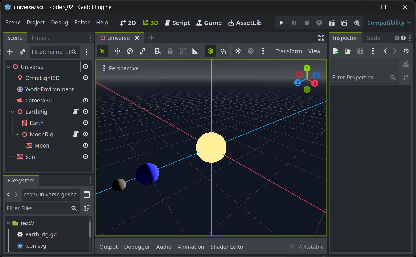
Introduction to Rendering and Shaders in Godot
The Rendering Pipeline
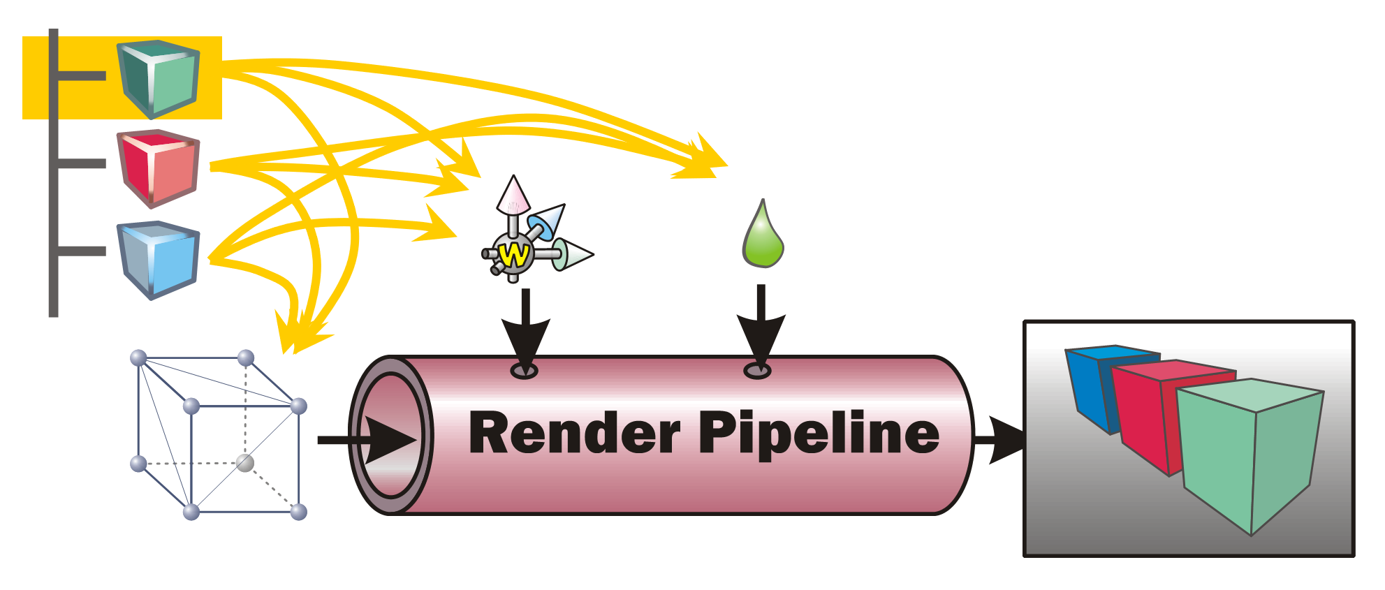
In order to render a picture from the data contained within the scene tree (or scene graph) in a game engines such as Godot, all data needs to be prepared and presented to the rendering pipeline. This is done by traversing the scene graph. During this process, each node within the scene is visited once and all the data it contains is sent to the rendering pipeline. A typical scene graph traversal is performed “depth first”, that is, whenever a node with children and siblings is currently visited, the next step will be to first visit its list of children and then continue with its next sibling.
Information such as the transformation (position, rotation, scale) as well as material settings are used to control the state of the rendering pipeline. The geometry (the meshes) present at the various scene nodes is directly “pumped” through the pipe. The pipeline’s task is then to generate a pixel image out of the geometry under the various current settings (also called the render state).
🪛 TODO
Imagine (or better, generate) a scene with hierarchies (such as a simple solar system) and perform a depth-first traversal with pen and paper. In which order are the scene nodes visited?
Render Pipeline Sub Processes
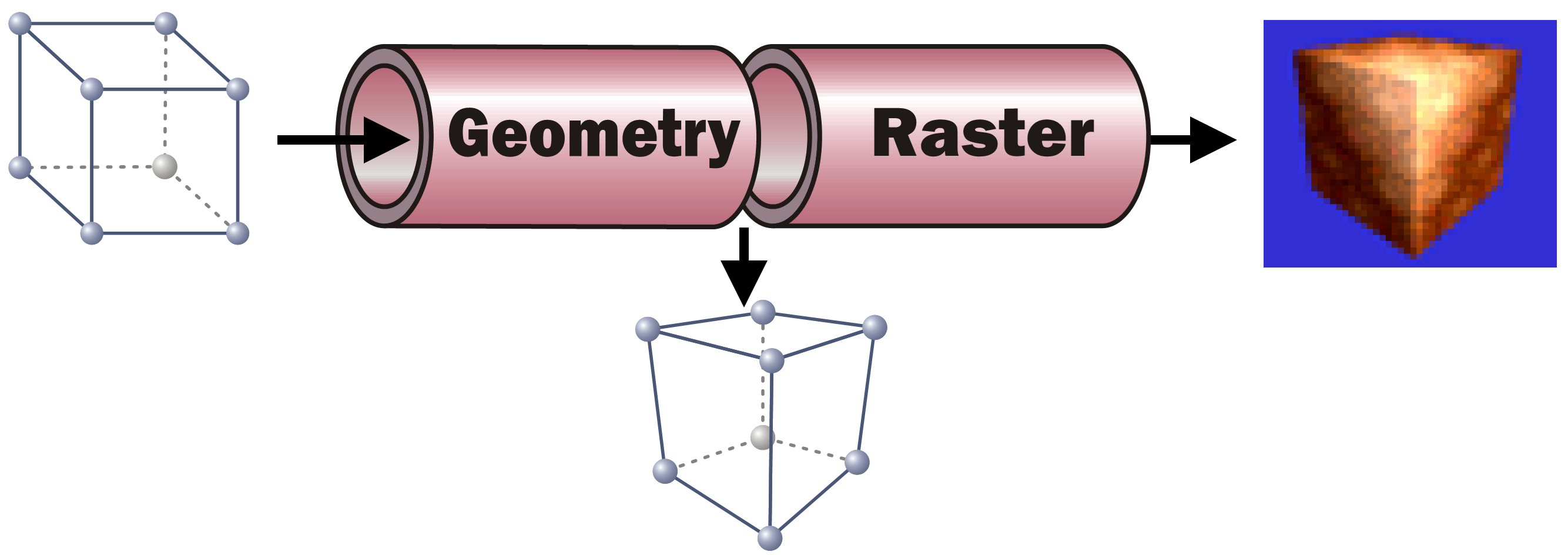
While this task can be broken down in quite a number of individual steps, each performed one after the other, we will only look at two sub-processes performed within the rendering pipeline here:
The Geometry part takes each incoming vertex with its (x, y, z) coordinates present in Model Space (the coordinates that the vertex was assigned when it was modeled, e. g. in Blender’s Edit Mode). It then converts the vertex’ coordinates into Screen Space. To to this, it applies all transformations present in the path from the scene root to the model. In addition it performs the (inverted) camera transformation. As a result, the vertex new coordinates are then in screen space, allowing to identify the pixel in the resulting image where the respective vertex will be positioned.
🪛 TODO
In the above solar system example, what transformations must be applied to all vertices of the Moon mesh?
As the information which vertices span which triangles do not change, after the Geometry step each triangle of the geometry can be “placed” on the to-be-generated pixel image.
With the knowledge which pixels in the resulting pixel images will be covered by which triangle, each of these pixels can now be assigned a color. This is the task of the Raster part. For each pixel a color calculation is performed, typically taking into account the pixel’s Normal (where the mesh surface at the given screen pixel is “looking at”), the lighting situation (where is light coming from? In which intensity and color?), the material’s base color (its albedo) and/or, if present, the texture(s) to use for the material, the texture coordinate (UV) and possible vertex colors present at the screen pixel in question. For any of that information only present at the mesh’s vertices (such as normal, UV, vertex colors…), a weighted average is calculated for the pixel based on the distance of the pixel to the containing triangle’s vertices. All the pixel-related information present as an input to calculate an individual pixel are called a Fragment.
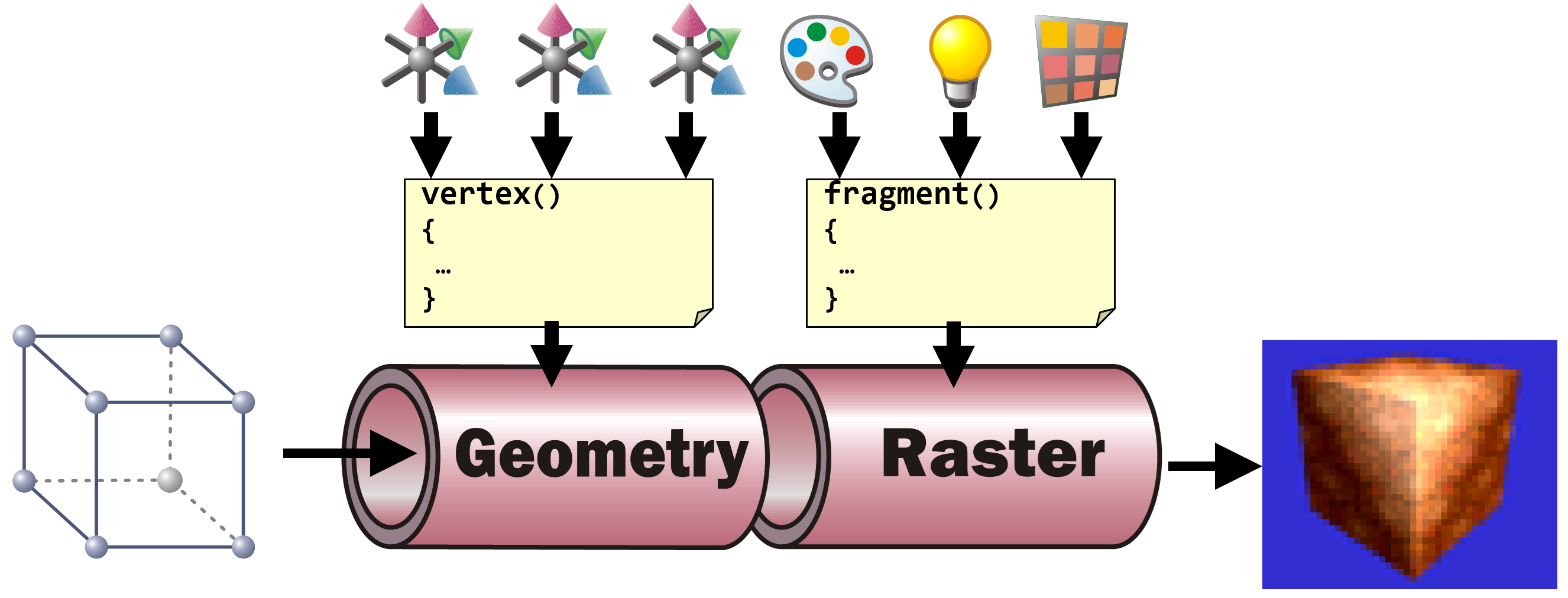
Shaders in Game Engines
In game engines, the exact operations to be performed to transform each vertex in the Geometry part and to calculate each fragments resulting pixel color are described in the materials stored in the scene graph. When using standard materials (such as in Godot), the shader code to use is defined by the engine. All a user has to do is to set the parameters (the transformations on each node as an input to the vertex shader and the various material settings such as albedo, transparency, roughness, emissive, … as input to the fragment shader).
Most engines allow users to define their own shader code together with their own set of shader parameters. In addition, most engines allow shader authors to access the standard shader input variables such as transformations given by the scene hierarchy and their transformations, the light settings, etc.
Shaders in Godot
Godot users can define their own shaders using a ShaderMaterial. This type of resource can be applied everywhere, where a material can be set, e.g. in the material setting for a mesh’s surface.
A ShaderMaterial must be given the file name of the shader code (with the “.gdshader” extension). When creating a new shader code file, an empty shader is created.
shader_typespatial;voidvertex(){// Called for every vertex the material is visible on.}voidfragment(){// Called for every pixel the material is visible on.}
Although both, vertex and fragment shaders contain an empty implementation, the shader already performs vertex transformation according to the scene settings and a simple pixel color calculation.
To switch off the vertex transformation, add
render_modeskip_vertex_transform;
to the top of the shader.
To switch off any color calculation, add
render_modeunshaded;
to the top of the shader.
🪛 TODO
Read the Godot Shader documentation and toy around with some simple shader settings.
In the vertex shader (with skip_vertex_transform set), implement your own vertex transformation by multiplying each vertex and normal with the ModelView matrix:
Add a fraction of the normal to the vertex resulting in the geometry appearing thicker or thinner depending on how big the fraction is.
In the (unshaded) fragment shader, set the resulting color of the current fragment/pixel by applying a three-dimensional color (rgb, e.g. green: (0, 1, 0)) value scaled by the angle between a light direction directly from the current camera’s viewing direction and the fragment’s normal to the Albedo
ALBEDO=vec3(0,1,0)*dot(vec3(0,0,1),NORMAL);
Make the parameters such as the “thickness” used in the vertex shader or the base color or even the light direction in the fragment shader uniform variables and see how they can be controlled within Godot’s User Interface.
In Real-Time rendering many visual effects result from a combination of the same mesh being passed through the rendering pipeline more than once with each of these passes having a different shader performing the rendering.
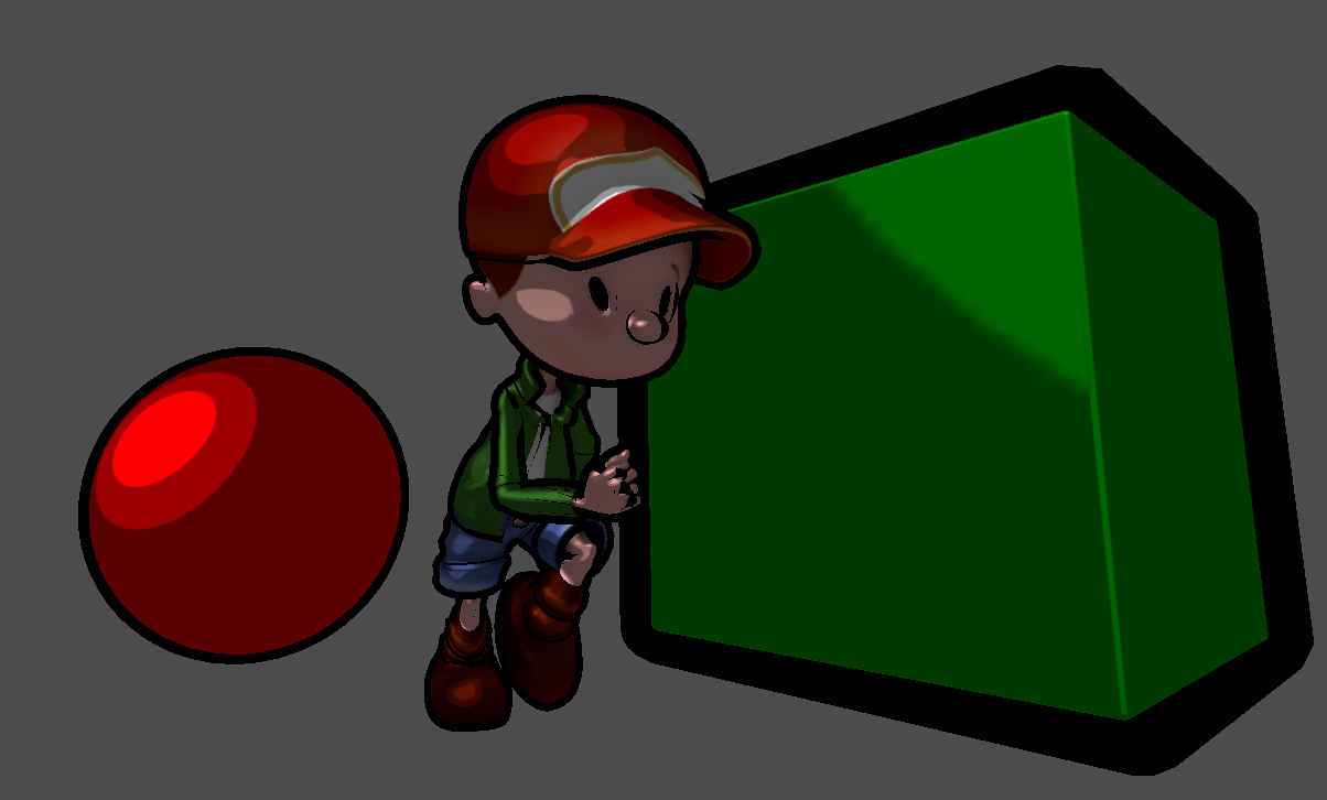
To simulate the impression of a hand-drawn image in comic-book-style, we can combine two render passes.
The first pass (cell pass) renders the geometry with usual transformation (no other than the transformation performed in Godot’s standard vertex shader). In the fragment shader, the object’s base color (either one color for the entire object or a color looked up from a texture accompanying the model) is shaded (darkened) in one of a very small number of discrete different brightness levels (e.g. three: light, medium, dark). This simulates the effect how a comic painter tries to visualize lighting: lacking a huge number of differently shaded color pencils for each color, they will draw the cell-like impression with hard transitions from one brightness level to the next.
The second pass (outline pass) inflates the geometry in the vertex shader using the “normal-trick” from the last lesson. The result is entirely painted in black (or a user-defined color) in the fragment shader. This will generate the dark outline around the objects.
It might have sounded more intuitive to first mention the outline pass and then the cell pass, because the color is somewhat expected to paint over the inflated black silhouette, we will find out that it does not play a role in which order the passes are performed since making the cell-colored pixels replace the black outline will be realized purely by having the colored geometry being placed in front of the black inflated geometry within 3D space. Let’s find out how this is accomplished:
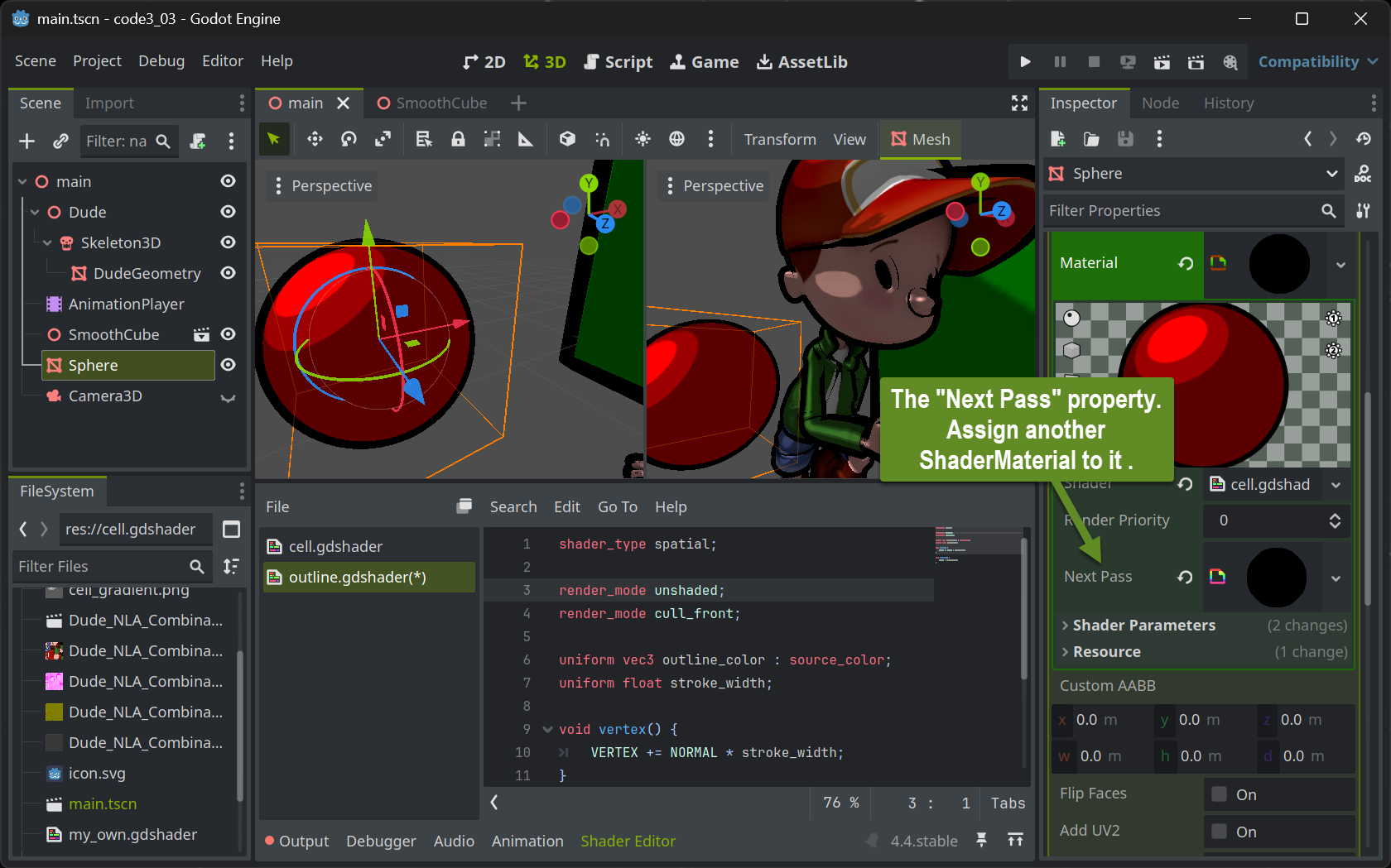
Multipass Rendering in Godot
Setting up multipass rendering in Godot is easy: Each ShaderMaterial resource allows to have a Next Pass property set. Simply assign another ShaderMaterial to that and you have the geometry associated with the outer ShaderMaterial travel twice through the rendering pipeline.
The Outline shader
Implementing the outline shader is straightforward. The vertex shader is configured to perform the standard transformation (NOrender_mode skip_vertex_transform!!). The code blows up the geometry by adding a fraction of the normal to each vertex. The amount of this fraction will then become the stroke width and can be set by users when implemented as a uniform.
The fragment shader is even simpler: With render_mode unshaded set, no lighting calculation at all is performed. Instead, each pixel is assigned the same color. Preferably black or dark colors will generate the comic-bookish outline look .
The most interesting part is the solution to how the black pixels of the silhouette are positioned behind the colored pixels from the cell pass. This is done by painting only the “rear-sided” triangles - those which are facing away from the camera. This way the (rather) concave inside of a half shell of the geometry is painted in black which will then be filled with the colored geometry. To achieve this, the cull mode which normally culls all triangles facing away from the viewer is reverted by the statement render_mode cull_front at the top of the shader.
The Cell Shader
To achieve the cell like look, we need to map the direction a pixel is looking at in 3D space (its normal) to one of the available brightness levels. There are many ways how this can be accomplished. We will use a 2D lookup table that’s easy to create and in addition gives us some creative headroom to define the look.
We create the 2D lookup table as a 2D pixel image that will be used as a texture in the cell pass’ fragment shader. Using an image painting program, we can paint a comic-like (cell-shaded) sphere. Typically one would draw a highlight using nested cells with increasing brightness at some upper left or right part of the sphere.
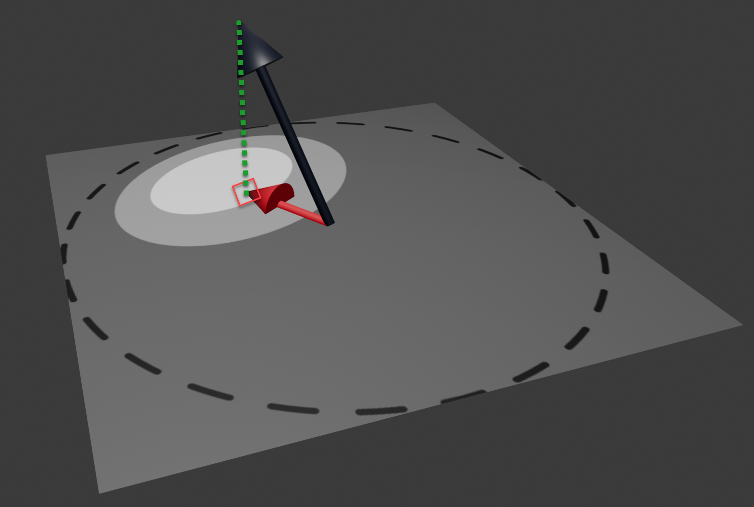
The sphere itself is not displayed as it is better to fill the entire square texture with the lowest brightness level. To generate the image, draw a helper circle (or imagine one) fitting exactly into the square texture and make sure not to paint any brightness highlights outside that circle. Make sure to NOT export that helper circle (the dotted line in the above image) to your shader texture. We will call this texture the gradient.
In the cell pass’ fragment shader we can use the normal at the to-be-rendered pixel to select which of the brightness cells should be used by projecting the normal onto the gradient texture and use the brightness of the texture pixel found there.
The black normal in the above image is (by calculation) positioned in the middle of the gradient texture and scaled to not exceed the gradient texture even when it would be in the image plane itself. Then it is projected (green dotted line) onto the image yielding texture coordinates to look up the pixel in the gradient texture. The (gray scale) color found there is used to multiply (shade) the object’s base color.
The shader accomplishing this has nothing to do in the vertex shader (other than the standard shader would do). The texture lookup in the gradient with the scaled and translated normal yields the cell gray scale color value. This is then combined with a given overall base color (albedo) and any given color texture associated with the object using a texture lookup with the UV coordinates averaged from the UVs provided at the mesh’s vertices.
Lighting
Goal
We first get familiar with the code, then we implement basic lighting calculations.
Assignment
Use the repository from last time and follow the instructions in the slides:
means that the code is already in the repository and you just need to look at it.
means you can copy-paste the code and it should work.
means that you need to create a new file
indicates that you need to do more than just copy-paste the code.
In any case you need to understand what you are doing.

